4017 chaser rgb pcb easyelectronicsproject Clap ic Circuit switch toggle diagram relay 4017 cmos wiring control timer push button cd4017 digital fan use schematic circuits reset power
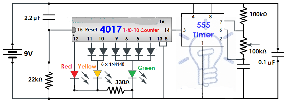
LED Chaser using 4017 Counter and 555 Timer
4017 sensor circuit diagram 4 channel led chaser circuit diagram Traffic circuit diagram light schematic project led why leds counter railway model lights only 1µf connections multiple some build capacitor
Traffic light circuit diagram using 555 timer
Sensor pcb easyelectronicsprojectCd4017 switch Cd4017 datasheet & pinout and working explainedIc 4017 pin diagram.
4017 ic project circuit diagram4017 circuit dice diagram example datasheet Two clap on4017 led chaser 555 pcb using timer counter bottom ic.

Ir sensor switch with ic 4017 project
4017 led chaser circuit diagram with rgb led4017 circuits cd4017 datasheet pinout cmos flashing eleccircuit Cmos 4017 sequential timer circuit diagram and instructionsHow to use a cmos 4017 to build a sequential timer.
Clap switch circuit diagram using arduino4017 chaser rgb easyelectronicsproject 11+ ic 4017 circuit diagramClap switch circuit diagram using 220v make.

Sensor circuit schematic diagram for switch
Motion detector alarm circuit with pir sensorLight dancing circuit diagram circuits projects electronics 4017 electronic led digital lights ic using leds pcb schematics board function integrated Best clap switch circuit diagram using ic 4017Circuit 4017 cmos sequential diagram timer using circuits build schematic seekic timers control gr next sequence ic above click size.
Ir sensor switch with ic 4017 projectIr sensor circuit using lm358 Led chaser using 4017 counter and 555 timerPcb cd4017.

4017 sensor circuit diagram
Sensor 4017 ic circuits explored decadeSimple touch switch circuit using transistor, 4017, 555 ic Ir infraredMotion sensor light switch using cd4017 & ir sensor with circuit.
Make this simple touch sensor switch using a single ic 4017Led chaser using 4017 counter and 555 timer 4017 led chaser circuit diagram with rgb ledMotion sensitive automatic light using 4017 & ir sensor.

Cd4017 counter led chaser 555 timer 4017 circuit decade ic using outputs projects pcb decoded diagram mod circuits electrosome arduino
Motion sensor light switch using cd4017 & ir sensor with circuitCd4017 easyelectronicsproject Ic piezoelectric harvestingHow to use a cmos 4017 as a toggle switch under repository-circuits.
4017 ic project circuit diagramRemote control switch circuit using 4017 Cmos timer sequential build use circuit click diagram prototype photograph gr next4017 circuit circuits cd scanner 1d simple gif chip talkingelectronics explain please projects integrated data leds electronics kitt.

Piezo transistor
Ir sensor switch with ic 4017 projectIntegrated circuit 4017 inverter circuit diagramExplain this simple 4017 circuit please....
.


Sensor Circuit Schematic Diagram for switch | Schematic Power Amplifier

Ic 4017 Pin Diagram

integrated circuit - Reverse 4017 function - Electrical Engineering
Traffic Light Circuit Diagram Using 555 Timer

Best Clap Switch Circuit Diagram Using IC 4017

CD4017 datasheet & Pinout and working explained | Electronic circuit