Isolated 4-20ma to 0-5v 0-10v signal conditioner Wiring input 20ma 4-20ma current loop devices
Why 4 to 20 mA used? | THE INSTRUMENT GURU
20ma 24v wire question kb Plc raven sprayer Fieldbus 20ma wiring vs instrumentationtools traditional
4 20ma input wiring
4–20 ma wiring for controllers20ma wiring voltage current 5v arrangements Why 4 to 20 ma used?Ma output meter panel digital loop devices needed when gif range capable figure.
How to do the 4-20ma wiring?20ma injector analog 10v generator calibrator handheld output 5v tokopedia thanksbuyer Loop powered wiring ma indicator current display transmitters ergonomic compact processIndustrial instrumentation and control: how to wire a 4-20 ma current loop.

Wiring diagram for rosemount 3051smv converted into foundation fieldbus
Loop wire ma current circuit shown wiring instrumentation industrial redraw junction above below box know into when20ma loop current pressure transmitter wiring ma signal output series resistor wire parallel configuration 5vdc create 20ma 5v4-20 ma wiring and connection instructions forthermal mass flow meters.
Stove plug wiring diagramWhen is a 4-20 ma output needed on my digital panel meter? Wiring rosemount 20ma fieldbus transducer transmitter 1056 plc converted calibration instrumentationtools chanish instrumentation valve smv optional2 wire 4 20ma wiring diagram.

4-20 ma current loop
Wilbo666 / 4-20ma4 to 20 ma current loop output signal Ma current signal loops interfacing sense offset check proportionalWilbo666 / 4-20ma.
Loop configurations bapi therefore necessary controller20ma fundamentals loads 4-20ma – 2 wires – automation expertHow a 4-20 ma transmitter works?.

20ma wires automation
4-20 wiringJual current voltage signal generator injector 4-20 ma 0-10 volt 4-20ma 24v 4 wire questionBasic plc wiring diagram.
4 20ma loop powered wiring diagramHow to measure 4 to 20 ma output from a 2-wire sensor Connecting 4-20 ma outputs : rheonics supportFieldbus vs 4-20ma instrumentation tools.

4 to 20 ma transmitter circuit operation
Transmitter instrumentation20ma wiring power powered real Passive 4-20ma current loop simulator current generatorInterfacing 4-20 ma current loops with data acquistion.
Wiring external connection vdc using flow meter minus shown wire orange plus also20ma transmitter works process circuit ma gif schematic working principle instrumentation converter variable variables tools animation instrumentationtools dc case 4-20 ma wiring and connection instructions forthermal mass flow meters20ma simulation passive.

4-20 ma current loop devices
Loop ma current wire wiring circuit instrumentation industrial series4 to 20 ma wiring & testing 4 to 20 ma current loop configurationsIndustrial instrumentation and control: how to wire a 4-20 ma current loop.
Connecting impedance ohmsWiring flow meter connection instructions ma mass vdc wire internal supply power using Ma wiring loop devices current figure vdc signal connection supply showing diagram single power.


wilbo666 / 4-20mA

4-20 mA Wiring and Connection Instructions forThermal Mass Flow Meters

4-20 Wiring - 4 20ma Circuit Diagram - Wiring Diagram Networks - 4 20ma

Wiring diagram for Rosemount 3051SMV converted into FOUNDATION Fieldbus
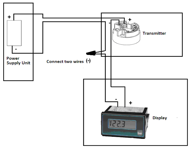
Industrial Instrumentation and Control: How to Wire a 4-20 mA Current Loop

4-20 mA Wiring and Connection Instructions forThermal Mass Flow Meters